Manufacturer & Exporter of Various Process Equipments In Stainless Steel (SS), Heat ExchangerS, Reactors, Special Purpose Assemblies
Manufacturer & Exporter of Various Process Equipments In Stainless Steel (SS), Heat ExchangerS, Reactors, Special Purpose Assemblies
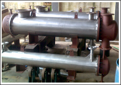
Shell and Tube Heat Exchangers are one of the most popular types of exchangers.
A shell and tube exchanger consists of a number of tubes mounted inside a cylindrical shell. Two fluids can exchange heat, one fluid flows over the outside of the tubes while the second fluid flows through the tubes. The fluids can be single or two phase and can flow in a parallel or a cross counter flow arrangement.
The shell and tube exchanger consists of four main parts:
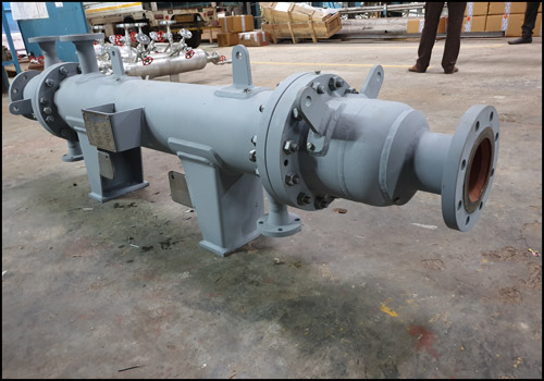
Front Header: This is where the fluid enters the tube side of the exchanger.
Rear Header: This is where the tube side fluid leaves the exchanger or where it is returned to the front header in exchangers with multiple tube side passes.
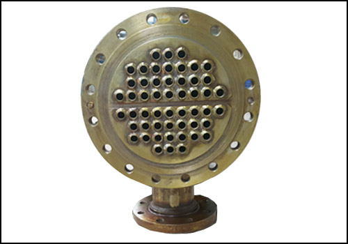
Tube bundle: This comprises of the tubes, tube sheets, baffles and tie rods, etc. to hold the bundle together.
Shell: This contains the tube bundle.
Selection of Exchanger Geometry:
Tube outside diameter: For the process industry, 19.05 mm (3/4") tends to be the most common.
Tube wall thickness: Tube wall thickness can be calculated as per ASME sec. VIII, Div.1.
Tube length: For a given surface area, the longer the tube length the cheaper the exchanger, although a long thin exchanger may not be feasible.
Tube layout: 45 or 90 degree layouts are chosen if mechanical cleaning is required, otherwise a 30 degree layout is often selected because it provides a higher heat transfer and hence smaller exchanger.
Tube pitch: The smallest allowable pitch of 1.25 times the tube outside diameter is normally used unless there is a requirement to use a larger pitch due to mechanical cleaning or tube end welding.
A Number of tube passes: This is usually one or an even number (not normally greater than 16). Increasing the number of passes increases the heat transfer coefficient but care must be taken to ensure that the tube side pv2 is not greater than about 10,000 kg/ms2.
Shell diameter: Standard pipe is normally used for shell diameters up to 610 mm (24"). Above this, the shell is made from rolled plate. Typically shell diameters range from 152 mm to 3000 mm (6" to 120").
Baffle type: Single segmental baffles are used by default but other types are considered if pressure drop constraints or vibration is a problem.
Baffle spacing: This is decided after trying to balance the desire for increased crossflow velocity and tube support (smaller baffle pitch) and pressure drop constraints (larger baffle pitch). TEMA provides guidance on the maximum and minimum baffle pitch.
Baffle cut: This depends on the baffle type but is typically 45% for single segmental baffles and 25% for double segmental baffles.
Nozzles and impingement: For shellside nozzles the pv2 should not be greater than about 9000 in kg/ms2. For tubeside nozzles the maximum pv2 should not exceed 2230 kg/ms2 for noncorrosive, nonabrasive single phase fluids and 740 kg/ms2 for other fluids. Impingement protection is always required for gases which are corrosive or abrasive, saturated vapors and two phases mixtures. Shell or bundle entrance or exit areas should be designed such that a pv2 of 5950 kg/ms2 is not exceeded.
Materials of Construction: In general, shell and tube exchangers are made of metal, but for specialist applications (e.g., involving strong acids or pharmaceuticals), other materials such as graphite, plastic and glass may be used.
Thermal Design:
The thermal design of a shell and tube exchanger is an iterative process which is normally carried out using computer programs or excel programs developed in-house. In order to calculate the heat transfer coefficients and pressure drops, initial decisions must be made on the sides the fluids are allocated, the front and rear header type, shell type, baffle type, tube diameter and tube layout. The tube length, shell diameter, baffle pitch and number of tube passes are also selected and these are normally the main items that are altered during each iteration in order to maximize the overall heat transfer within specified allowable pressure drops.
The main steps in the calculation are given below:
1. Calculate the shell side flow distribution
2. Calculate the shell side heat transfer coefficient
3. Calculate tube side heat transfer coefficient
4. Calculate tube side pressure drop
5. Calculate wall resistance and overall heat transfer coefficient
6. Calculate the mean temperature difference
7. Calculate the area required.
8. Compare area required with the area of assumed geometry and allowed tubeside and shell side
pressure drop with calculated values.
9. Adjust assumed geometry and repeat calculations until Area required is achieved within the
allowable pressure drops.
Mechanical Design:
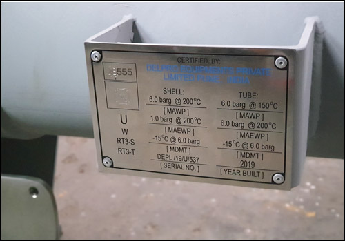
The mechanical design of a shell and tube heat exchanger provides information on items such as shell thickness, flange thickness, etc. These are calculated using a pressure vessel design code such as the Boiler and Pressure Vessel code from ASME (American Society of Mechanical Engineers) and the British Master Pressure Vessel Standard, BS 5500. ASME is the most commonly used code for heat exchangers and is in 11 sections. Section VIII, Div.1 of the code is the most applicable to heat exchangers along with Sections II-Materials and Section V-Non Destructive Testing and Section IX are also relevant.
Both ASME and BS5500 are widely used and accepted throughout the world.
The popularity of shell and tube exchangers has resulted in a standard nomenclature being developed for their designation and used by the Tubular Exchanger Manufacturers Association (TEMA)